
eUTRAN Parameters Description and Planning
Basic Cell Parameter: ECGI Planning
- ECGI = PLMN + Cell Identity
- PLMN = MCC + MNC
- Cell Identity = eNodeB ID + Cell ID
- Parameter Description
- ECGI : It indicates the E-UTRAN cell global identifier.
- MCC: It indicates the country code of the mobile subscriber.
- MNC: Its indicates the code of network used by the mobile subscriber.
- Cell Identity: It is of 28 bits. The former 20 bits indicate the eNodeB ID, and the latter 8 bits indicate the cell ID.
Basic Cell Parameter: ECGI Planning

1. MCC: It is of 3 bits. Its value ranges from 0 to 999.
2. MNC: It is of 2 bits or 3 bits. Its value ranges from 0 to 999.
3. eNodeB ID: Its value ranges from 0 to 1048575. The eNodeB ID is unique to every eNodeB in the same PLMN. When you are planning the eNodeB ID, you need to take the network scale into account. Generally speaking, there is small-sized network, standard-sized network, large-sized network and shared network.
4. Cell ID: It is unique to every cell in the same eNodeB. Its value ranges from 0 to 255.
Basic Cell Parameter: eNodeB ID
1. Standard-Sized Network
The eNodeB ID appears to be ABCDEF in a standard-sized network.
The first two figures (namely AB) indicate the city where the eNodeB is located.
The last figure (namely F) indicates whether it is an indoor eNodeB or an outdoor eNodeB. If the last figure appears to be “0”, it is an indoor eNodeB. Otherwise, it is an outdoor eNodeB.
2. Large-Sized Network
In most cases, the eNodeB ID appears to be ABCDEF.
The first two figures (namely AB) indicate the city where the eNodeB is located.
Different AB combination indicates different cities. The AB combination can indicate at most 90 cities, each of which can hold 9999 eNodeBs at most. Sometimes, the network may cover more than 90 cities. In this case, use every AB combination to indicate two or more than two cities. Each city can hole at most 5000 eNodeBs.
The last figure (namely F) indicates whether it is an indoor eNodeB or an outdoor eNodeB. If the last figure appears to be “0”, it is an indoor eNodeB. Otherwise, it is an outdoor eNodeB.
In some special cases, if F appears to be “9”, it is a remote eNodeB.
3. Shared Network If it is a shared network, for example the TDD-FDD network in Hi3G project, you will use 6-digit eNodeB ID (ABCDEF).
The first figure (namely A) indicates the network schema. “1” stands for the TDD network, and “5” stands for the FDD network.
The second figure (namely B) indicates the city where the eNodeB is located.
The third figure (namely C) may indicate the administrative region where the eNodeB is located.
The last figure (namely F) indicates whether it is an indoor eNodeB or an outdoor eNodeB. If the last figure appears to be “0”, it is an indoor eNodeB. Otherwise, it is an outdoor eNodeB
Basic Cell Parameter: CP
- CP Selection for Physical Channel
- Parameter Description
- This parameter indications the cyclic prefix(CP) of the OFDM symbol,which is used to determine the total number of OFDM symbols within one slot. When this parameter is set to normal cyclic prefix, it implies that seven OFDM symbols are available within one slot. When this parameter is set to extended cyclic prefix, it implies that six OFDM symbol are available within one slot.
- Value Range and Step Length
- Value Range: enum (normal cyclic prefix, extended cyclic prefix)
- Default Value: normal cyclic prefix
- Configuration Principles
- The cp is dependent on the multipath delay of a radio channel. In the presence of either a large mutipath delay or a large cell radius, extended cyclic prefix is recommended.
- The extended cyclic prefix option can suppress radio interference caused by multipath delay, but suffering from lower system capacity, and therefor it is recommended that you set it to the default value.
Basic Cell Parameter: Bandwidth
- Downlink System Bandwidth
- Parameter Description
- This parameter indicates the system bandwidth in the downlink, which is used to determine the frequency domain location of the downlink physical channel as well as downlink frequency allocation.
- Value Range and Step Length
- Value Range: enum (6, 15, 25, 50, 75, 100) Unit RB
- Default Value: 100
- Configuration Principles
- This parameter is dependent on the frequency bandwidth acquired by a mobile operator. The downlink system bandwidth can either be identical to or different from the uplink system bandwidth.
- Modifying this parameter can have an impact on downlink resource allocation
- Uplink System Bandwidth
- Parameter Description
- This parameter indicates the system bandwidth in the uplink , which is used to determine the frequency domain location of the uplink physical channel as well as uplink frequency allocation.
- Value Range and Step Length
- Value Range: enum (6, 15, 25, 50, 75, 100) Unit RB
- Default Value: 100
- Configuration Principles
- This parameter is dependent on the frequency bandwidth acquired by a mobile operator. The system uplink bandwidth can either be identical to or different from the downlink system bandwidth.
- Modifying this parameter can have an impact on uplink resource allocation
Basic Cell Parameter: Transmit Power
- Cell Max Transmit Power
- lParameter Description
- This parameter specifies the maximum available transmit power.
- Value Range and Step Length
- Value Range: float (0, …, 50) step 0.1 Unit dBm
- Default Value: 43
- Configuration Principles
- The default value is intended to be used in the following environment:

Basic Cell Parameter: Transmit Power
- Cell Transmit Power
- lParameter Description
- This parameter specifies the used transmit power.
- Value Range and Step Length
- Value Range: float (0, …, 50) step 0.1 Unit dBm
- Default Value: 43
- Configuration Principles
- For the environment information about the use of the default value, see page 13(Cell Max Transmit Power).
- This parameter is dependent on the cell radius and the planned downlink throughput at the cell edge. The greater the cell radius or the planned downlink throughput at the cell edge, the greater the value of this parameter is required.
- Cell-specific Reference Signals Power
- Parameter Description
- This parameter specifies the absolute power value of the cell reference signal for each resource element.
- Value Range and Step Length
- Value Range: int (-60, …, 50) Unit dBm
- Default Value: 6
- Configuration Principles
- This parameter is dependent on cell coverage. The greater the cell coverage, the greater the value of this parameter is required. This parameter should be used for ensuring cell coverage while achieving the maximum power.
- A reference signal power value should be properly tuned in accordance with the required power of the downlink control channel at the cell edge based on the link estimation calculated by using such radio parameters as cell type ,cell radius, and antenna height.
Part 2 Tracing Area Planning
Tracing Area Planning : Paging Process
- The idle UE can monitor the paging message by means of discontinuous reception (DRX). It detects whether the PDCCH carries the P-RNTI on the paging occasion of specified paging frame. The detection results will tell the UE whether this PDSCH carries paging message.
- a) If the PDCCH carries the P-RNTI, the UE receives the data from the PDSCH based on the PDSCH parameters.
- b) If the PDCCH does not carry the P-RNTI, the UE changes into the dormant status.
- Within a DRX period, the UE can receive the PDCCH data when the paging occasion appears, and then receive the PDSCH data based on the actual requirements.
- As specified by the LTE physical layer protocol, the radio frame No. repetition period is 1024. Every radio frame is divided into ten sub-frames. In this regard, if the UE wants to know the accurate location of the PDCCH to be monitored, it needs to work out the radio frame No. for this PDCCH, and then work out the paging occasion (PO) for this radio frame number.
Tracing Area Planning : Paging Parameters
- DRX Cycle for Paging
- Parameter description
- This parameter specifies the DRX cycle for paging purposes.
- Value Range and Step Length
- Value Range: enum (32, 64, 128, 256) Unit; subframe
- Default Value:128
- Configuration Principles
- When the UE is in idle state but the DRX is being used, the UE needs to monitor a P-RNTI in a paging occasion every DRX cycle.
- Modifying this parameter can have an impact on other UEs being in idle state.
- nB used to derive the Paging Frame and Paging Occasion
- Parameter description
- nB is used to derive the paging frame and paging occasion, as defined in TS36.304
- Value Range and Step Length
- Value Range: enum (4T, 2T, T, 1/2T, 1/4T, 1/8T, 1/16T, 1/32T)
- Default Value:T
- Configuration Principles
- T represents a paging cycle. For example 2T indicates two default paging cycles.
- It indicates the paging attempts made by a radio frame. Its value can be 4T
- The Parameter to Detemine BCCH Modification Period
- Parameter description
- This parameter is used to determine the BCCH modfication period(BCCH modification period=N*DRX cycle length for paging).The purpose of this constraint is to ensure that all the UEs being in idle state can monitor the system broadcast change message.
- Value Range and Step Length
- Value Range: enum (2,4,8,16)
- Default Value:4
- Configuration Principles
- The greater this parameter, the longer the system message is updated.This can have a adverse impact on real-time message update.
- The smaller this parameter, the shorter the system message is updated. This can cause the UE to monitor the system Info Value Tag more frequently
Tracing Area Planning

- TAC: It indicates a tracing area in a PLMN. It is used to manage the UE location and find the desired UE.
- 1. The TAC is unique in a PLMN.
- 2. A cell must belong to a tracing area (TA) exclusively. When you configure the TAC, you need to consider the quantity of cells in this TA.
- 3. The bonding relation between the TAC and the cell is determined by the cell size, cell type (high-speed cell or low-speed cell) and TA list configuration.
- Principles
- 1.Determine the size of tracing area based on the UE paging capability and the network .
- 2.Avoid frequent IRAT cell re-selection and LAU/TAU.
- 3.Take the geographical features into account.
- a) Do not place the tracing area boundary in the heavy-traffic area (e.g. downtown area, or central business district). Place the boundary in the low-traffic area (e.g. suburban area, or factories).
- b) The tracing area boundary should be orthogonal or diagonal to the road. Moreover, keep the overlapped part between tracing areas away from the area where UE moves in high speed.
- c) Do not place different tracing area boundaries in the same small area. Otherwise, the UE may frequently update the tracing area information or perform handovers between these tracing areas.
- 4.Take the traffic increase tendency into account so as to provide tracing areas with proper paging capacity, traffic capacity and expandability of the tracing area.
Part 3 PCI Planning
PCI Planning (1)

PCI Planning (2)
- Principles
- 1)If there are cell A, cell B and cell C, the cell A and the cell B make up a group of neighboring cells while the cell B and cell C make up another group of neighboring cells, then the cell A and the cell C must use different PCIs.
- 2)When you allocating PCIs to different cells controlled by the same eNodeB, all these PCIs should comply with the mod3 principle. Additionally, consider the mod3 principle when you allocating the PCI to the cell and its nearest neighboring cell.
- 3)Cells sharing the same PCI should be far from each other as much as possible.
Part 4 PRACH Planning
Random Access Parameter
1.Cell High-speed Attribute
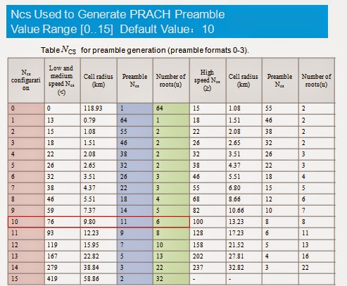
2.Ncs Used to Generate PRACH Preamble
3.Logical Root Sequence Start Number Used to Generate PRACH Preamble
4.Number of Non-dedicated Random Access Preambles
5.Size of Random Access Preambles Group
6.Threshold of Selecting Preamble Group
7.Message Power Offset for Group B
8.the Initial RB Number for Random Access Preambles
9.PRACH Configuration Index
10.Initial Power for Preamble of PRACH
11.Power Ramping Step for PRACH
12.Max retransmit number for PRACH
13.TTI Window Size for PRACH Response
14.Max Number of Messages HARQ Transmissions
15.MAC Contention Resolution Timer
16.Dedicated Preamble Life Time
Physical Random Access Channel (PRACH) is mainly used during the random access process.
The functions of random access in LTE include the following:
-Obtaining UL synchronization during initial access and handovers.
-Assigning a unique C-RNTI for the UE during initial network access establishment.
An example
is when the status is changed from RRC_IDLE to RRC_CONNECTED.
Two scenarios are involved in the random access process:
Scenario I: Contention-Based Access
Scenario II: Contention-Free Access

There are two types of random access:
- Synchronized Random Access
- Non-synchronized Random Access
- Contention-based access (The UE selects a random preamble)
- Contention-free access (The eNodeB assigns a dedicated preamble to the UE.)
- RRC_IDLE (initial access)
- Break of radio link (initial access)
- Handover (random access)
- RRC_CONNECTED, the downlink data is arriving but the uplink is out-of-synchronization. (random access)
- RRC_CONNECTED, the uplink data is arriving but the uplink is out-of-synchronization, or the scheduling request is received from the PUCCH (random access)
Contention-free Access: applicable to No.3 and No.4 triggers.


- PRACH Format Selection
- Considering the resources occupied by the PRACH, and the
- coverage area and features of macro cells, please select format 0
- when configuring the initial network.
- PRACH Root μ Sequence Selection Principles:
- (1) The root μ sequences between neighboring cells should be different.
- (2) The distance between cells whose root μ sequence should meet requirements.
- (3) Select the root μ sequence with smaller cyclic shift for the high speed scenario.
- The Ncs in the high speed scenario should be proper so as to address the impact left to the peak data rate check from the cyclic shifting caused by frequency offset.
- The recommended value is given in the protocol.


Neighboring Cell Planning
- The neighboring cell planning aims to ensure voice quality and performance of the entire network as the UEs on the cell edge can be handed over to their neighboring cells with the best signals.
- The principles are as follows:
- 1.Normally, the geographically adjacent cells are configured as neighboring cells;
- 2.Oftentimes, the neighboring cell relation is bilateral; at times, the neighboring cell relation is unilateral;
- 3.The number of neighboring cells should be proper. That is, either excessive or few neighboring cells are improper. With excessive neighboring cells, the UE measurement might be overloaded; with few neighboring cells, evitable call drops and handover failures might occur without neighboring cells. At most 16 neighboring cells are recommended for initial configuration.
- 4.The neighboring cell planning should be based on the drive test and actual radio environment. For suburban and rural areas, to ensure possible handovers, neighboring cells should be configured even if the inter-site distance is long.

- Usually, the entire LTE network adopts the same frequency band. For example, 20 MHz bandwidth is used for the entire network. To avoid ICIC, you need to allocate different bands for different cells. Ensure that two cells with great overlapped coverage should better not use the same frequency resources.
- Currently, frequency allocation includes four modes:
- Based On Same-Frequency
- Based on SFR(Non Exclusive IC)
- Based on SFR(Exclusive IC)
- Based on Differ-Frequency

Static ICIC Realization
- Static SFR
- As shown in the left figure, the whole frequency band is divided into three equal part. f1, f2 and f3 indicate the outer cell of three sectors.

- Static FFR
- As shown in the right figure, the whole frequency band is divided into four parts. It is similar to the case that the f1 in SFR mode is divided into three equal parts, each of which serves as the outer cell area of three sectors. In this way, cell edge users (CEUs) are separated from cell center users (CCUs), reducing the interference from the side lobe users in the neighboring cell to the CCUs of the service cell.


No comments:
Post a Comment