Analog & Digital Modulation:
Modulation in electronics and communications is a process of superposition of two electric waves, one carrier and a high frequency, and a low-frequency portable wave. Example of radio broadcasting: The radio station sends the announcer's voice as a low-frequency wave on a high-frequency electromagnetic wave. And receive them with the radio and the electronic circuit special disassociation of the waves from each other, and amplify the wave electrically portable and connect to the loudspeaker, we hear the announcer from the radio.
Inclusion or overlay is between the carrier (high-frequency) and a "portable" wave that is said to have the modified signal and carries the information to be transferred.
Decoding) is the reverse process where the modified signal is extracted from the carrier. The appropriate device is called the deformation remover.
The device that is fit for inclusion and to remove the modification is said to be "modem".
The inclusion of the signal is one of the most important processes in communication technology for its ability to absorb very high frequencies. The embedding technology is used in several systems such as GSM, Bluetooth, TV, GPS and other systems.
Analog Modulation:
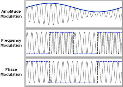
Analog modulation is the basis of modulation processes and is also called inclusion for simplification. There are three main technologies in analogue modulation including amplitude or amplitude, frequency embedding and phase embedding.
Include capacity:
Amplitude Modulation (AM):
In this technique the value of the carrier frequency signal is changed as a linear function with the transmitted signal value (core) and is easily characterized by its design and ease of decoding. But including the amplitude makes the signal very noisy and sometimes loses if the signal is not strong enough.
Include frequency:
Frequency Modulation (FM):
This modulation is characterized by noise isolation as the change is in the frequency of the carrier signal itself as a linear function with the value of the transmitted signal. However, it consumes a much wider range than the modulated modulation technique and the modulators and decoders are relatively complex.
Include phase:
Phase Modulation (PM):
In this type of modulation, the angle or phase of the carrier frequency signal changes linearly with the value of the base signal. Although this technique carries the advantages of bandwidth inclusion in a wider bandwidth than its predecessor, the problem lies in the complexity of the hardware in both modulation and decoding, which limits its applications.
Digital inclusion:
Digital Modulation:
Digital Modulation Unlike digital transmitters as in wired local networks, so digital information is sent in its digital mode, the wireless transmitter can not transmit information digitally, so it must be converted to analogue signals through one of the following basic adjustment methods:
Adjustment for displacement of capacitance.
ASK (amplitude-shift keying).
Adjust the frequency offset.
FSK (frequency-shift keying).
Adjust phase offset.
PSK (phase-shift keying).
Modify the minimum offset
Adjust the minimum Gaussian offset (GMSK).
Include Capacity Offset:
Amplitude Shift Keying (ASK):
The method of embedding displacement is one of the simplest methods of digital adjustment, where binary digital information 0 and 1 are represented in two different capacities. As shown in the picture, 0 is represented as zero and 1 is represented as a. This type of modification has some disadvantages for its sensitivity to transmission errors such as interference, noise, and multi-track signal dispersion. Therefore, the signal integrity in the case of wireless transmission can not be guaranteed with such errors.
Include frequency offset:
Frequency Shift Keying (FSK):
The method of including FSK is one of the most widely used digital modulation methods. In this way, the binary numeric information 0 and 1 is represented by a static capacity signal and the frequency is changed for each case. As in the picture, case 1 is represented at f1 and zero at f2. This type of modification is less sensitive to transmission errors than interference, noise and dispersion of multi-track signal.
Include phase offset:
Phase Shift Keying (PSK):
In this type of adjustment, a change in the phase angle occurs at 180 ° at each change of digital information from 0 to 1 or vice versa with the installation of the capacitance and frequency value. This type of frequency is less sensitive to transmission errors than interference, noise and dispersion to the multi-track signal compared to the previous two types, but the transmitter and receiver circuits are more complex. If you modify the rack using one bit of the input signal, the phase modifies 180 ° and the speed is 1200 bits / second. If the rack is modified using 2 bits of the input signal, the phase is adjusted by 90 ° and the speed is 2400 bits / second. If the rack is modified using 3 bits of the input signal, the phase modifies by 60 ° and the speed is 4800 bits / second. If the rack is modified using 4 bits of the input signal, the phase modifies by 45 ° and the speed is 9600 bits / second. If the carrier is modified using 6 bits of the input signal, the phase modifies by 45 ° and the speed is 28800 bits / second. If the rack is modified using 8 bits of the input signal, the phase modifies by 30 ° and the speed is 56600 bits / second.


keep sharing
ReplyDeletePhone Systems BC
Phone Systems Vancouver