Search Telecom Hub in Google to find us any were
Showing posts with label LTE. Show all posts

Friday, 20 October 2017

What is LTE ?

  • LTE stands for Long Term Evolution, LTE is a standard for high speed wireless communication for mobile device which are based on technologies like GSM/EDGE etc.
  • It increases the capacity and speed using a different radio interface together with core networks.
  • There are different frequency and bands used in different countries.
  • This technology is designed to provide IP-based data ,voice etc which having streaming speed at least 100 Mbit per second up to as fast as 1 Gbit per second.


Goals of LTE :

  • The goal of LTE is to increase the capacity and speed of wireless networks by using new DSP (digital signal processing) techniques and modulations which were developed around the turn of the millennium.
  • It also use to improve the spectral efficiency, lowering the cost and improving the services.
  • A further goal of LTE was the redesign and simplification of the network architecture to an IP-based system with significantly reduced transfer latency compared to the 3G architecture.

Advantages of LTE :

  • Mobile carriers from all around the globe have upgraded or starting to upgrade their networks to the latest technology.
  • Long Term Evolution networks are the mobile connectivity equivalent to what broadband is to dial up connectivity. By using This technology it is now possible to do anything on the Internet using mobile phones as if we are connected to a fixed broadband line.
  • This technology focuses on increasing both the upload and download speeds compared to its predecessors. LTE is mobile technology which has created an environment in which application developers can create more options that will better the user’s experience.
  • This technology is an all IP system that turn calls into digital data and sends them over the networks.
  • This technology will decreases traffic on networks & improving your call sessions and conversations. When there is lack of capacity LTE can in real time reallocate bandwidth between different callers.
  • Due to this mobile technology more people will access faster Internet through their mobile phones than fixed lines.

How does LTE works ?

  • Current method of moving or transferring the data on internet protocol get changed because of LTE.
  • Now we can send large amount of data through it. the major benefit of the LTE i.e reduces the latency in data transfer.
  • In GSM we uses the technology called as Time Delay Duplex(#TDD) And in CDMA it uses Code Division Duplex(CDD). Both CDD and TDD are the method of-coding information which transfer across the airwaves.
  • CDD is faster than TDD but world is operate on GSM so GSM is improved to the HSPA i.e High Speed Packet Access.

LTE technology based on GSM/EDGE and HSPA.

  • LTE incorporates the Digital Signal Processing which is used for better adjudicate the data packet transfer.
  • Long Term Evolution -travels like radio waves with extra ordinary speed with same bandwidth transfer large amount of data.
  • Long Term Evolution – made the interface and network improvement which helps to increase data capacity and speed.
  • Long Term Evolution – reduces the transfer delay that means data moves or transfer faster.


LTE and Internet of Things.

  • LTE is two or three times more efficient than 3G network and 20 times more efficient than 2G.
  • During the analysis it has estimated that data costing a dollor to send over 2G network . while it can sent over an LTE network for a mere five cent.
  • Because of this powerful economic incentive, operators around the world are aggressively re-farming their 2G as well as 3G spectrum and move quickly to LTE.
  • IoT friendly LTE chipset are the support for the new wave of LTE device development ,and best solutions are flexible, efficient and low cost. Today there are may chipset modules available which have been designed for the IoT.
  • Highly optimized for M2M and IoT devices these new solution provide all features and functionality required to build robust,long life LTE devices for many application at low cost.

Thursday, 27 July 2017

LTE/SAE Network Architecture/Interfaces.
What is LTE
 LTE (Long Term Evolution) is known as the evolution of radio access technology conducted by 3GPP.
◦ The radio access network will evolve to E-UTRAN (Evolved UMTS Terrestrial Radio Access Network), and the correlated core network will evolved to SAE (System Architecture Evolution).


What can LTE do
p  Flexible bandwidth configuration: supporting 1.4MHz, 3MHz, 5MHz, 10Mhz, 15Mhz and 20MHz.
p  Peak date rate (within 20MHz bandwidth): 100Mbps for downlink and 50Mbps for uplink.
p  Provide 100kbps data rate for mobile user (up to 350kmph).
p  Circuit services is implemented in PS domain: VoIP.
p  Lower cost due to simple system structure.

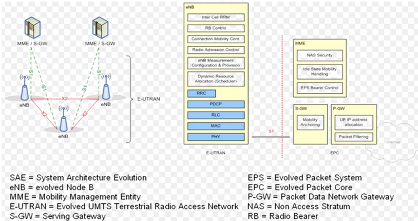
LTE/SAE Network Architecture


LTE Interfaces
S1-MME :- Reference point for the control plane protocol between E-UTRAN and MME.
S1-U:- Reference point between E-UTRAN and Serving GW for the per bearer user plane tunneling and inter eNodeB path switching during handover.
S3:- It enables user and bearer information exchange for inter 3GPP access network mobility in idle and/or active state.
S4:- It provides related control and mobility support between GPRS Core and the 3GPP Anchor function of Serving GW. In addition, if Direct Tunnel is not established, it provides the user plane tunneling.
S5:- It provides user plane tunneling and tunnel management between Serving GW and PDN GW. It is used for Serving GW relocation due to UE mobility and if the Serving GW needs to connect to a non-collocated PDN GW for the required PDN connectivity.
S6a:- It enables transfer of subscription and authentication data for authenticating/authorizing user access to the evolved system (AAA interface) between MME and HSS.
Gx:- It provides transfer of (QoS) policy and charging rules from PCRF to Policy and Charging Enforcement Function (PCEF) in the PDN GW.
S8:- Inter-PLMN reference point providing user and control plane between the Serving GW in the VPLMN and the PDN GW in the HPLMN. S8 is the inter PLMN variant of S5.
S9:- It provides transfer of (QoS) policy and charging control information between the Home PCRF and the Visited PCRF in order to support local breakout function.
S10:- Reference point between MMEs for MME relocation and MME to MME information transfer.
S11:- Reference point between MME and Serving GW.
S12:- Interface Reference point between UTRAN and Serving GW for user plane tunneling when Direct Tunnel is established. It is based on the Iu-u/Gn-u reference point using the GTP-U protocol as defined between SGSN and UTRAN or respectively between SGSN and GGSN. Usage of S12 is an operator configuration option.
S13:- It enables UE identity check procedure between MME and EIR.
SGi:- It is the reference point between the PDN GW and the packet data network. Packet data network may be an operator external public or private packet data network or an intra operator packet data network, e.g. for provision of IMS services. This reference point corresponds to Gi for 3GPP accesses.
SGs:- Reference point between MSC and MME for CSFB procedure. 


Functional Split between E-UTRAN and EPC 
The E-NodeB functions:
Functions for Radio Resource Management: Radio Bearer Control, Radio Admission Control, Connection Mobility Control, Dynamic allocation of resources to UEs in both uplink and downlink (scheduling);
IP header compression and encryption of user data stream;
Selection of an MME at UE attachment when no routing to an MME can be determined
from the information provided by the UE;
Routing of User Plane data towards Serving Gateway;
Scheduling and transmission of paging messages (originated from the MME);
Scheduling and transmission of broadcast information (originated from the MME or O&M);
Measurement and measurement reporting configuration for mobility and scheduling; 

The MME  (Mobility Management Entity):
NAS signalling;
NAS signalling security;
Idle mode UE Reachability (including control and execution of paging retransmission);
Tracking Area list management (for UE in idle and active mode);
PDN GW and Serving GW selection;
MME selection for handovers with MME change;
SGSN selection for handovers to 2G or 3G 3GPP access networks;
Roaming;
Authentication;
Bearer management functions including dedicated bearer establishment;
deals with the control plane. It handles the signaling related to mobility and security for E-UTRAN access.
The Serving Gateway (S-GW) hosts the following functions:
The gateways (Serving GW and PDN GW) deal with the user plane. They transport the IP data traffic between the User Equipment (UE) and the external networks.
The Serving GW is the point of interconnect between the radio-side and the EPC. As its name indicates, this gateway serves the UE by routing the incoming and outgoing IP packets.
Packet routeing and forwarding;
The PDN Gateway (P-GW) hosts the following functions:
The PDN GW is the point of interconnect between the EPC and the external IP networks. These networks are called PDN (Packet Data Network), hence the name. The PDN GW routes packets to and from the PDNs.
The PDN GW also performs various functions such as IP address / IP prefix allocation or policy control and charging.


HSS (Home Subscriber Server)
The HSS (Home Subscriber Server) is the concatenation of the HLR (Home Location Register) and the AUC (Authentication Center) – two functions being already present in pre-IMS 2G/GSM and 3G/UMTS networks. The HLR part of the HSS is in charge of storing and updating when necessary the database containing all the user subscription information, including (list is non exhaustive):
· User identification and addressing – this corresponds to the IMSI (International Mobile Subscriber Identity) and MSISDN (Mobile Subscriber ISDN Number) or mobile telephone number.
· User profile information – this includes service subscription states and user-subscribed Quality of Service information (such as maximum allowed bit rate or allowed traffic class).
The AUC part of the HSS is in charge of generating security information from user identity keys. This security information is provided to the HLR and further communicated to other entities in the network. Security information is mainly used for:
· Radio path ciphering and integrity protection, to ensure data and signaling transmitted between the network and the terminal is neither eavesdropped nor altered.
The PCRF (Policy and Charging Rules Function)
 The PCRF server manages the service policy and sends QoS setting information for each user session and accounting rule information.
Provide QoS information to packet gateway 
Dynamically manage and control data sessions. Example: For VoIP session, PCRF will initiate dedicated bearer dynamically
Determine charging policy for packets.

Tuesday, 10 January 2017

Thursday, 5 January 2017

LTE GSM UMTS WCDMA RF jobs India bangalore

LTE Weekend Drive on 7th Jan at Bangalore Location

Location : Bangalore

Experience : 3-8years


Candidates who attend drive on this 7th i.e saturday can only apply

Strong knowledge in LTE/UMTS/GPRS with basic IMS knowledge is desired
Experience with Wireless Data Core networks, Architecture, Protocols and Interfaces
Good understanding of Wireless Operators end-end Network
Experience with LTE core system interfaces and protocols such as S1-MME, S1-U, S6a, S11, S5/S8, Rx, NAS, S1-AP, RRC, GTPv2c, GTP-U, SGs-AP is desired
Working Knowledge in any of UMTS/GPRS Protocols such as NBAP, RNSAP, RANAP, BSSAP+ and GTP is preferred
Excellent Understanding of Rel 8/Rel 9/Rel 10 3GPP standards
Expertise in creating test plans for system level, subsystem level and feature level testing
Understanding of Software testing Life cycle
Good Knowledge in TCP/UDP, IP protocols and understanding of basic OSI model
Company Profile:
Millennium Technosoft Ltd.