
LTE/SAE Network Architecture/Interfaces.
—What is LTE?
◦ LTE (Long Term Evolution) is known as the evolution of radio access technology conducted
by 3GPP.
◦ The
radio access network will evolve to E-UTRAN (Evolved UMTS
Terrestrial Radio Access Network), and the correlated core network will evolved to SAE
(System Architecture Evolution).
What can LTE do?
p Flexible bandwidth configuration: supporting 1.4MHz, 3MHz,
5MHz, 10Mhz, 15Mhz and 20MHz.
p Peak date rate (within 20MHz bandwidth): 100Mbps for downlink
and 50Mbps for uplink.
p Provide 100kbps data rate for mobile user (up to 350kmph).
p Circuit services is implemented in PS domain: VoIP.
p Lower cost due to simple system structure.


LTE/SAE Network Architecture

LTE Interfaces
—S1-MME :- Reference point for the
control plane protocol between E-UTRAN and MME.
—S1-U:- Reference point between
E-UTRAN and Serving GW for the per bearer user plane tunneling and inter eNodeB path switching during handover.
—S3:- It enables user and bearer
information exchange for inter 3GPP access network mobility in idle and/or
active state.
—S4:- It provides related control and
mobility support between GPRS Core and the 3GPP Anchor function of Serving GW.
In addition, if Direct Tunnel is not established, it provides the user plane
tunneling.
—S5:- It provides user plane tunneling
and tunnel management between Serving GW and PDN GW. It is used for Serving GW
relocation due to UE mobility and if the Serving GW needs to connect to a
non-collocated PDN GW for the required PDN connectivity.
—S6a:- It enables transfer of
subscription and authentication data for authenticating/authorizing user access
to the evolved system (AAA interface) between MME and HSS.
—Gx:- It provides transfer of (QoS) policy and charging rules from PCRF
to Policy and Charging Enforcement Function (PCEF) in the PDN GW.
—S8:- Inter-PLMN reference point
providing user and control plane between the Serving GW in the VPLMN and the
PDN GW in the HPLMN. S8 is the inter PLMN variant of S5.
—S9:- It provides transfer of (QoS) policy and charging control
information between the Home PCRF and the Visited PCRF in order to support
local breakout function.
—S10:- Reference point between MMEs
for MME relocation and MME to MME information transfer.
—S11:- Reference point between MME and
Serving GW.
—S12:- Interface Reference point between UTRAN
and Serving GW for user plane tunneling when Direct Tunnel is established. It
is based on the Iu-u/Gn-u reference point using the GTP-U protocol as defined
between SGSN and UTRAN or respectively between SGSN and GGSN. Usage of S12 is
an operator configuration option.
—S13:- It enables UE identity check
procedure between MME and EIR.
—SGi:- It is the reference point between
the PDN GW and the packet data network. Packet data network may be an operator
external public or private packet data network or an intra operator packet data
network, e.g. for provision of IMS services. This reference point corresponds
to Gi for 3GPP accesses.
—SGs:- Reference point between MSC and MME for CSFB procedure.
—SGs:- Reference point between MSC and MME for CSFB procedure.
Functional Split between E-UTRAN and EPC
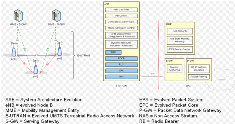
The E-NodeB functions:
◦Functions for Radio Resource
Management: Radio Bearer Control, Radio Admission Control, Connection Mobility
Control, Dynamic allocation of resources to UEs in both uplink and downlink
(scheduling);
◦IP header compression and encryption
of user data stream;
◦Selection of an MME at UE attachment
when no routing to an MME can be determined
from the information provided by
the UE;
◦Routing of User Plane data towards Serving Gateway;
◦Scheduling and transmission of paging
messages (originated from the MME);
◦Scheduling and transmission of
broadcast information (originated from the MME or O&M);
◦Measurement and measurement reporting
configuration for mobility and scheduling;
The MME (Mobility
Management Entity):
◦NAS signalling;
◦NAS signalling security;
◦Idle mode UE Reachability (including
control and execution of paging retransmission);
◦Tracking Area list management (for UE
in idle and active mode);
◦PDN GW and Serving GW selection;
◦MME selection for handovers with MME
change;
◦SGSN selection for handovers to 2G or
3G 3GPP access networks;
◦Roaming;
◦Authentication;
◦Bearer management functions including
dedicated bearer establishment;
◦deals with the
control plane. It handles the signaling related to mobility and security for
E-UTRAN access.
The Serving
Gateway (S-GW) hosts the following functions:
—The gateways (Serving
GW and PDN GW) deal with the user plane. They transport the IP data traffic
between the User Equipment (UE) and the external networks.
The Serving GW is the point of interconnect between the radio-side and the EPC.
As its name indicates, this gateway serves the UE by routing the incoming and
outgoing IP packets.
—Packet routeing and forwarding;
The PDN Gateway
(P-GW) hosts the following functions:
—The PDN GW is the point of
interconnect between the EPC and the external IP networks. These networks are
called PDN (Packet Data Network), hence the name. The PDN GW routes packets to
and from the PDNs.
—The PDN GW also performs various
functions such as IP address / IP prefix allocation or policy control and
charging.
HSS
(Home Subscriber Server)
—The HSS (Home
Subscriber Server) is the concatenation of the HLR (Home Location Register) and
the AUC (Authentication Center) – two functions being already present in
pre-IMS 2G/GSM and 3G/UMTS networks. The HLR part of the HSS is in charge of
storing and updating when necessary the database containing all the user
subscription information, including (list is non exhaustive):
—· User
identification and addressing – this corresponds to the IMSI (International
Mobile Subscriber Identity) and MSISDN (Mobile Subscriber ISDN Number) or
mobile telephone number.
—· User profile
information – this includes service subscription states and user-subscribed
Quality of Service information (such as maximum allowed bit rate or allowed
traffic class).
—The AUC part of the
HSS is in charge of generating security information from user identity keys.
This security information is provided to the HLR and further communicated to
other entities in the network. Security information is mainly used for:
—· Radio path
ciphering and integrity protection, to ensure data and signaling transmitted
between the network and the terminal is neither eavesdropped nor altered.
The PCRF (Policy and
Charging Rules Function)
— The PCRF server manages the
service policy and sends QoS setting information for each user
session and accounting rule information.
—Provide QoS information to packet gateway
—Dynamically manage and control data
sessions. Example: For VoIP session, PCRF will initiate dedicated bearer
dynamically
—Determine charging policy for
packets.


Very useful information.
ReplyDeletecould you please send to me this PDF copy?
ReplyDeleteActually, I need this knowledge. That's why.
my email- snowwhitesin28@gmail.com
Very useful and informative
ReplyDelete